Drive the Stepper Motors & Control via Grbl and CNC Shield
Detailed description on how the stepper motor work and how to control it via the driver can be found through the external link here.
I. Deal with single one stepper
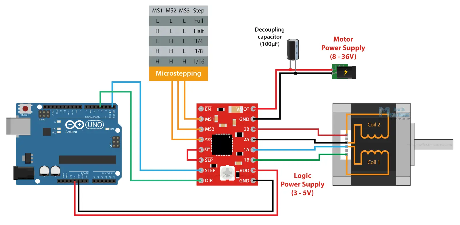
 Fig 1. An instruction on how to connect the A4988 driver with the stepper motor and the Arduino controller
Several different components will be needed here:
- Motor Power Supply: An adapter switching power supply charger, with 7 different voltage options ranging from 6V~24V, was adopted. A decoupling capacitor ($100\mu F$) was recommended to install to protect the board from voltage spike.
- Stepper Motor: Here we employed a NEMA17 with 1.5A for a maximum current limitation, $1.8^{\circ}$ for resolution of per step.
- Stepper Driver: A4988 from AZ-Delivery was used to drive the motor.
- Control Unit: Arduino Uno board is just enough.
VMOT and GND pins are used to connect the external motor power supply; VDD and GND pins are for the logic power supply from controller. As for Sleep and Reset pins, we should note that both of these pins are active low. The Sleep pin by default is HIGH state, but the RST pin is floating. That means in order to have the driver enabled, the easiest way is to just connect these two pins to each other, assuming we won’t use these pins functions. The Enable pin is also active low, so unless we pull it HIGH, the driver will be enabled.
Several important tips when connecting motors to drives:
Make sure which two wires make a phase of motor
The simplest way is to rotate the shaft of the stepper motor by hand, and then connect two wires to each other. If you connect two wires that make a phase, the rotation of the shaft would be a bit more difficult. Another way is to use a multimeter and check for continuity between the two wires. If you connect two wires that make a phase, you will have a short circuit and the multimeter will start beeping.
Match the current limit of driver and stepper
There’s a small trimmer potentiometer on the A4988 driver through which we can adjust the current limit. By rotating the potentiometer clockwise, the current limit raises, and vice versa. The first method involves measuring the reference voltage across the potentiometer itself and GND. A external motor power supply would not be needed for now. We can measure the reference voltage using a multimeter, and use that value in the following formula (work only for A4988) to calculate the current limit of the driver:
\[Current Limit = Vref/(8*Rcs)\]The $Rcs$ is the current sense resistance, depending on the manufacturer, the value is usually 0.05, 0.1 or 0.2 ohms (resistors are right next to the chip on driver board, and there’s a clear mark indicating the resistance stick on it, like “R100” or just a “0.1”).
The second method is to directly measure the current flow through the coils. We can skip the controller connection, but instead connect 5V to the Direction and the Step pins so that the motor stays active and holds one position. Then we can disconnect one line or coil from the motor, and connect it in series with an ammeter. In this way, once we power the driver with both the logic voltage, the 5V, and the power for the motor 12V in my case, we can read how much current is running through the coil.
MS1, MS2 and MS3 are for selecting the step resolution of the motor according to the Microstepping table. These three pins have pull-down resistors, so if we leave them disconnected, the driver will work in full-step mode. For selecting a different mircrostepping resolution we need to connect 5V to the appropriate pins according to this table.
OK, all that’s left to do is to connect the board, code on Arduino IDE and upload it. There are several encountered issues when I trying different application:
❓ Serial function seems always disturb the main control logic here. For example, the rotatory encoder won’t precisely work and output the readings on serial monitor when I manually rotate the encoder shaft, to control the motor to step by doing so. But it is wired everything goes smooth when the serial print function was deactivate. By the way, if we put the serial start function at the very beginning of the program, the motor shaft will just stuck (that is to say, temporarily ignore the initial speed we set for it) and step only after a speed regulation was input from the encoder or an external potentiometer.
❓ The stepper motor still making a changing noise even though the customized delay between steps has surpass the maximum I set (that is to say, slow the stepper) and no actual speed changes. It is wired and I wonder what actually happened in there, and the actual speed range of motor since it seems always shifting and hard to define.
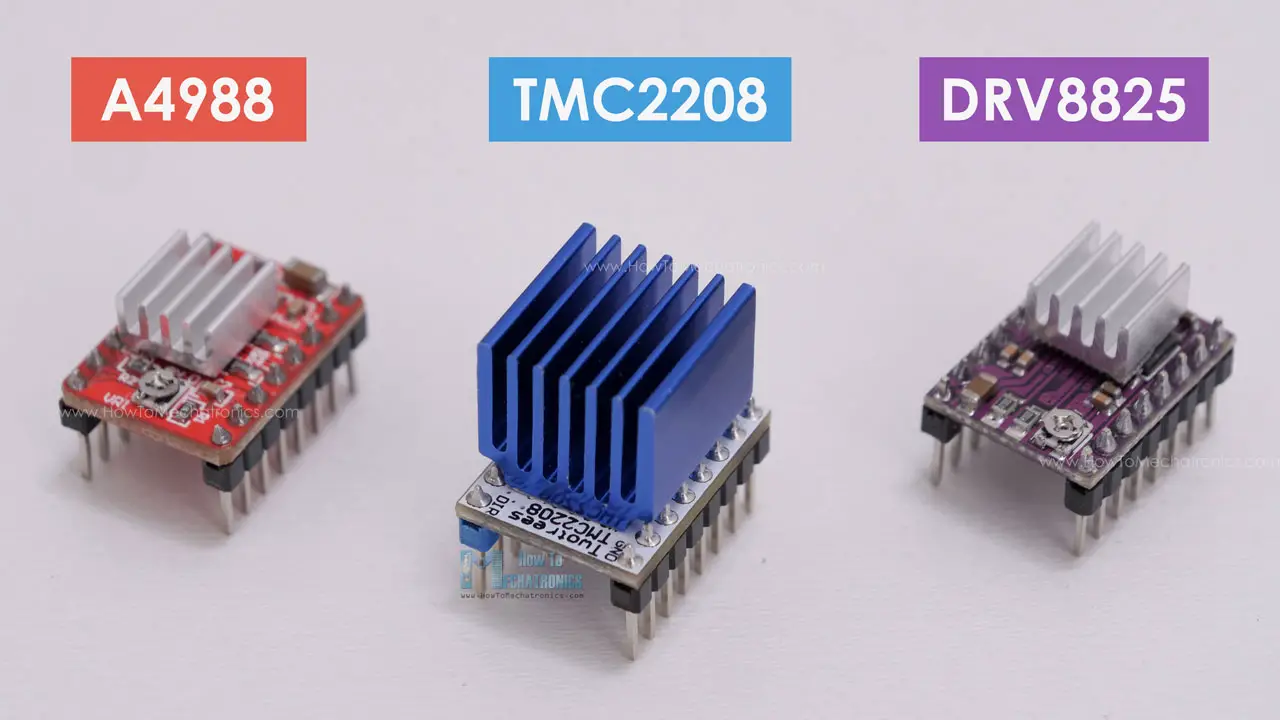
 Fig 2. Different stepper motor drivers
By the way, we can always try different stepper motor drivers here, like DRV8825 or TMC2208. TMC2208 is with a highest resolution of 256 microsteps and a higher current limit, and it drives the motors completely silently.
II. Deal with multiple steppers simultaneously
AccelStepper Library
1
2
3
4
5
6
7
8
9
10
11
12
13
14
15
16
17
18
19
20
21
22
// Creat stepper class instance, define the stepper motor and the pins that is connected to
AccelStepper stepper_1(1, 2, 5);   // (Typeof drive: with 2 pins, STEP pin, DIR pin)
AccelStepper stepper_2(1, 3, 6);
AccelStepper stepper_3(1, 4, 7);

MultiStepper steppersCtrl;    // Create instance of MultiStepper

long goposition[3];   // An array to store the target positions for each stepper motor

void setup(){
...
	stepper_1.setMaxSpeed(1000);    // Set maximum speed value for this stepper
...
	steppersCtrl.addStepper(stepper_1);    // Add certain stepper instance in multi ctrls
...
}
void loop() {
	goposition[0] = 800;    // 800 steps - full rotation with quater-step resolution
...
	steppersCtrl.moveTo(goposition);    // Set desired position, Calculate the required speed for all motors
	steppersCtrl.runSpeedToPosition();    // Steps, Blocks until all steppers are in position
}
runSpeedToPosition()blocks the code until the steppers reach their target position. If you don’t want to block the code and rather let it forward by every step, we could userun()instead.MultiStepperclass doesn’t support acceleration and deceleration.
1
2
3
4
5
6
7
8
9
10
11
12
13
14
15
16
17
18
AccelStepper stepper_(1, 2, 5);

void setup(){
	stepper_.setMaxSpeed(1000);    // Set maximum speed value for this stepper
	stepper_.setAccelaration(500);    // Set acceleration value for this stepper
	stepper_.setCurrentPosition(0);    // Set current position to 0 steps
...
}
void loop(){
	stepper_.moveTo(800);    // Set desired position
	stepper_.runToPosition();    // Move the motor to target position and it blocks till the end

	stepper_.moveTo(0);    // Move back to 0, set the target position
	while(stepper_.currentPosition() != 0){
		stepper_.run();    // non-blocking function
	}
...
}
III. CNC shield and Control via Grbl
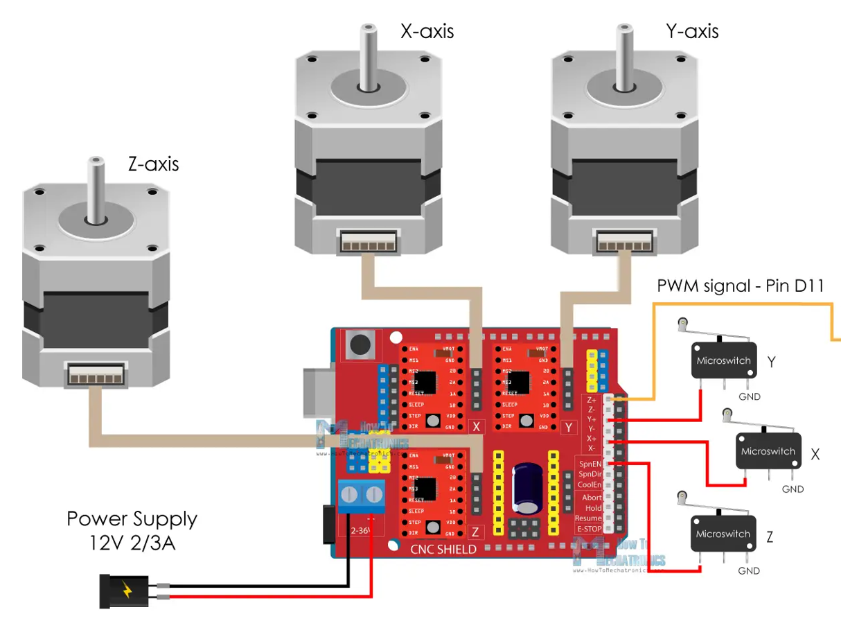
 Fig 3. Wire the components accordingly (stepper, limit switch, power supply, arduino uno and its CNC shield)
Add Grbl library into Arduino environment, regulate the
config.hand deactivate the homing along Z axis (in our case, it only needs two axis X and Y).1 2 3 4 5
// NOTE: The following are two examples to setup homing for 2-axis machines. // #define HOMING_CYCLE_0 ((1<<X_AXIS)|(1<<Y_AXIS)) // NOT COMPATIBLE WITH COREXY: Homes both X-Y in one cycle. // #define HOMING_CYCLE_0 (1<<X_AXIS) // COREXY COMPATIBLE: First home X // #define HOMING_CYCLE_1 (1<<Y_AXIS) // COREXY COMPATIBLE: Then home Y
Make sure the belt is with enough tension, otherwise, the homing procedure will not proceed. The limit switch will first try to detach instantly after it was activate by touching, and slowly move back right at the point where the touch happened. The distance was normally fixed, therefore if the belt is loose, the switch won’t successfully detached after certain steps.