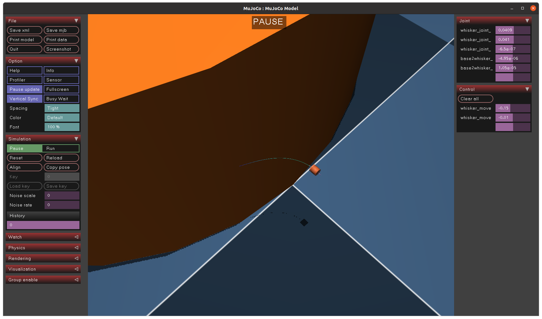
Deploy a Simulated Flexible Whisker Model in Mujoco
Simulation Model on Mujoco
Structure & Measurement
Build a whisker basement here first in the world body which was enabled to freely move in three directions (3DoF) : 2D translation on X- and Y-axis, 1D rotation around Z-axis. And secondly, a movable connector between whisker shaft and basement was built, serving a similar function as the magnet and those spring support device in real mechanical design. It was used to reflect the instantaneous rotation on shaft and output the proper measurement. We enabled it to move also in three directions (3DoF) : 2D translation on X- and Y-axis, 1D rotation around Z-axis.
Both of which were carefully regulate via some important parameters to ensure the stability (deduce the fluctuation during contact on whikser_base) and proper movement in certain range (the whisker_body was only used to reflect the moment caused by shaft deflection, so the stiffness and damping were set).
Flexible Whisker Shaft
The cable plugin discretizes an inextensible 1D continuum. It is intended to simulate the twist and bending of rods where the stretching in negligible compared to the other deformation modes.
We implement 40 parallel elasticity.cable elements to fabricate a whole flexible whisker shaft.
Parameters:
twist[Pa]: twisting stiffness.bend[Pa]: bending stiffness.flat[bool]: if true, the stress-equilibrium configuration is that of a straight cable; if false or unspecified, it is the configuration defined in the XML.vmax[N/m^2]: If greater than zero, the cable is colored using mechanical stresses; the value represent the maximum stress in the color scale.
1
2
3
4
5
6
7
8
9
10
11
12
13
14
15
16
17
18
19
20
21
22
23
24
25
26
27
28
29
30
31
32
33
34
35
36

	<!-- World Body -->
  <worldbody>
		...

		<!-- Whisker Basement -->
    <body name="whisker_base" pos="-0.005 0.1 0.175" axisangle="1 0 0 90">
	    ...
      <joint name="whisker_joint_x" type="slide" axis="0 0 1" damping="10" armature="0.1"/>
      <joint name="whisker_joint_y" type="slide" axis="1 0 0" damping="10" armature="0.1"/>
      <joint name="whisker_joint_z" type="hinge" axis="0 1 0" damping="1" armature="0.01"/>
      <!--"contype="0" conaffinity="0"": used to avoid the unknowable vibration of whisker when contacting the whisker base-->
      <geom type="cylinder" size="0.005 0.005" rgba=".8 .3 .1 .5" mass="0.1" contype="0" conaffinity="0" />

			<!-- Whisker Shaft -->
      <body name="whisker_body">
				...
        <joint name="base2whisker_x" type="slide" axis="0 0 1" damping="10" stiffness="1000" armature="0.01"/>
        <joint name="base2whisker_y" type="slide" axis="1 0 0" damping="10" stiffness="100" armature="0.01"/>
        <joint name="base2whisker_z" type="hinge" axis="0 1 0" damping="0.01" stiffness ="1" armature="0.00001"/>
        <geom type="cylinder" size="0.000125 0.01" rgba=".8 .3 .7 1" mass="0.005" contype="0" conaffinity="0" />

        <composite prefix="whisker" type="cable" curve="0 0 s" count="40 1 1" size="0.1 0 0" initial="none">
          <plugin plugin="mujoco.elasticity.cable">
            <config key="twist" value="40e9"/>
            <config key="bend" value="100e9"/>  <!-- https://www.ulbrich.com/alloys/nitinol-wire-astm-f2063/ -->
            <config key="vmax" value="0.001"/>
          </plugin>
          <joint kind="main" damping="0.0001" armature="0.00001"/>
          <geom type="capsule" size=".000125" rgba=".8 .3 .1 1" condim="1" density="6450"/>
        </composite>
      </body>

    </body>

  </worldbody>
Actuator & Sensor
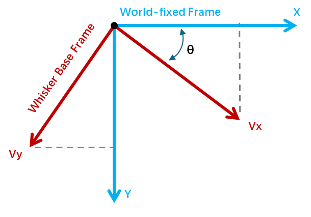
The control was mainly built based on an adjustable moving direction $\theta$ within the world-fixed frame of whisker, and two separate fixed linear velocity along X- and Y-axis on whisker base frame. The rotation was built via whisker_joint_z, a hinge. So the linear velocity under world-frame of whisker sensor will change with the rotation, according to the figure beside.
We also need an absolute position sensor on the whisker shaft’s tip, therefore to valid our previous tiptap estimate method and collect data to build a post-optimized characteristic model on current shaft’s tip position. BTW, the notation S_last would automatically index to the last cable component in the composite. Moreover, we have confirmed that the position under this situation was exactly corresponding to the actual tip point which locate at the endpoint of the last cable, not the middle, not the start point, since there’s still a length of 0.1 of this single element so it matters.
1
2
3
4
5
6
7
8
9
10
11
12
13
14
15
16
17
18
  <actuator>
    <!-- velocity control -->
    <velocity joint="whisker_joint_x" name="whisker_move_vel_x"/>
    <velocity joint="whisker_joint_y" name="whisker_move_vel_y"/>
    <plugin joint="whisker_joint_z" plugin="mujoco.pid" instance="pid" />
  </actuator>

  <sensor>
    <jointpos joint="base2whisker_x" name="base2whisker_x"/>
    <jointpos joint="base2whisker_y" name="base2whisker_y"/>
    <jointpos joint="base2whisker_z" name="base2whisker_z"/>
    <velocimeter site="vel_sensor" name="vel_sensor"/>

    <jointpos joint="whisker_joint_x" name="whisker_joint_x"/>
    <jointpos joint="whisker_joint_y" name="whisker_joint_y"/>
    <jointpos joint="whisker_joint_z" name="whisker_joint_z"/>
    <framepos objtype="site" objname="whiskerS_last" reftype="site" refname="vel_sensor" name="tip_pos"/>
  </sensor>
We also need an absolute position sensor on the whisker shaft’s tip, therefore to valid our previous tiptap estimate method and collect data to build a post-optimized characteristic model on current shaft’s tip position. BTW, the notation S_last would automatically index to the last cable component in the composite. Moreover, we have confirmed that the position under this situation was exactly corresponding to the actual tip point which locate at the endpoint of the last cable, not the middle, not the start point, since there’s still a length of 0.1 of this single element so it matters.
📌 In the simulation, it is actually a direct way to build unique mapping from instantaneous deflection moment to shaft tip position, since the tip position was already known by
framepossensor. However impossible for sensor in real world. We still need to calibrate the deflection profile first via grid-format touch by motorized stage and then, based on fitted polynomial profile, gradient descent method and pre-known length of shaft to manually extract tip data.

