Add AS5600 Encoder to for Linear Velocity Measurement
Magnet & Sensor Installation
We need a structure to hold the AS5600 sensor break-board on the back of NEMA18 stepper first. A little bearing is quite convenient to hold the board tight.
 Hold AS5600 on the back of NEMA17 stepper
A diametric magnetized cylindric magnet is needed. To make it easy to install on the shaft back-tip, I print another little component to hold it still from the disturbance of the around coil.
Finally, wire it up with any host MCU, here I used an Arduino nano and connect to PC. BTW, better to pull up the DIR port on AS5600 otherwise it would cause malfunction in I2C communication and fluctuation. Meanwhile, if DIR is connected to ground, the output value increases with clockwise rotation. If DIR is connected to VDD, the output value increases with counterclockwise
Coding Part
Check Magnet Presence
There are three different status of this encoder, according to the magnet presence:
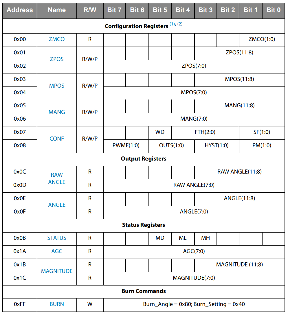
MHAGC minimum gain overflow, magnet too strong;MLAGC maximum gain overflow, magnet too weak;MDMagnet was detected. Start the measurement until it reaches theMD, 32 which equals to 100000 in binary. We could access it from the status register via address0x0B. BTW, the communication is based on I2C and 7-bit slave address of the AS5600 is 0x36 (0110110 in binary). There’s no need to bring it up again to the part of building connection byWire. It’s too easy.Read Raw Angle
The AS5600 magnetic rotary position sensor with a high-resolution 12-bit output. The raw angle digits was stored in the register of
0x0C(4 bits - last four bits - 11:8 Highbyte) and0x0D(8 bits - 7:0 Lowbyte). Highbyte have to be shifted to its proper place as we want to build a 12-bit number. The resolution:360 / (2^12)=0.087890625.1 2 3
highbyte = highbyte << 8; rawAngle = highbyte | lowbyte; degAngle = rawAngle * 0.087890625;
By the way, considering the minimum detectable rotary angle of $0.0878^{\circ}$, a microstepping setting of 3200 on stepper is decent enough, $360/3200 = 0.1125^{\circ}>0.0878^{\circ}$. If it is 6400 microstepping, the encoder won’t be able to detect the step, $360/6400 = 0.05625^{\circ} < 0.0878^{\circ}$.
Correct Angle & Check Quadrant
 Raw angle in clockwise direction
As far as I know, the raw angle is directly connected to the current state of magnet position, that is to say which direction the north pole was hold toward. It is non-zero I suppose, not like the start state would always be zero when you start up the sensor. We shall record the initial state, or to say angle, as the start point
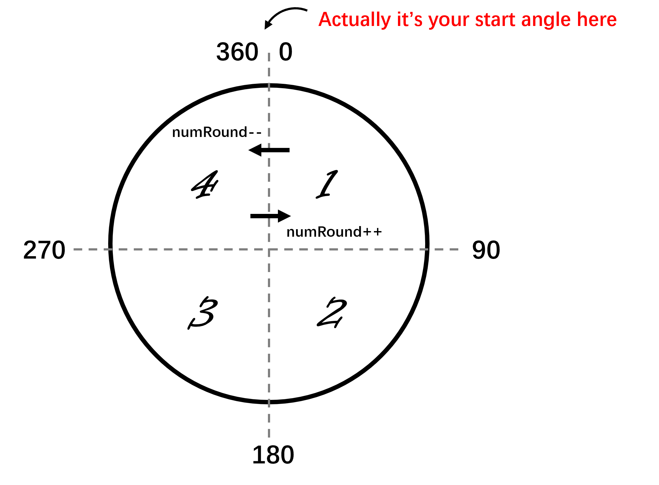
startAngleand correct the instantaneous input according to it. For example, considering $60^{\circ}$ as the start angle: 1) imagine the input was $340^{\circ}$, it would be fine, the rotary angle was incremented by clockwise; 2) imagine the input was $45^{\circ}$, there would be a problem, it run out the boundary of $0^{\circ}$ and the deviation $-15^{\circ}$ turned to be minus, even though it still runs by clockwise. Therefore a correction is necessary.1 2 3 4
correctedAngle = degAngle - startAngle; if (correctedAngle < 0){ correctedAngle = correctedAngle + 360; }
You can pretend it replace a $0^{\circ}$ (old frame) with any non-zero start angle (new frame) here. And then, detect a whole round by its quadrant, as it showed in the figure.
Finally, calculate the RPM
1
2
3
4
5
6
7
8
  timerdiff = millis() - rpmTimer;

  if (timerdiff > rpmInterval){
  	rpmValue = (60000.0 / timerdiff) * (totalAngle - recentTotalAngle) / 360.0;
  	stepRateFromRPM = rpmValue * 3200.0 / 60.0;
  	recentTotalAngle = totalAngle;
  	rpmTimer = millis();
  }
The only thing should be noticed here is
3200.0. It is our microstep setting of stepper. Here we only in charge of output the step rate, in $step/s$, a calibrated single step distance of stepper should be multiplied to it according to your ownGRBLconfiguration.

