Whisker Inspired Tactile Sensing for Contact Localization on Robot Manipulators
Original Paper: Whisker-Inspired Tactile Sensing for Contact Localization on Robot Manipulators
General Proposal
The basic objective of this work is to implement a non-intrusive perception method based on whisker sensor for robot arm, within a unstructured environment. To be specific, the motion of robot arm and sensor itself can’t cause disturbance on light weight free-standing objects in amidst clutter within a close range, meanwhile extract the 2D contour of different objects.
There’s two general challenges (features, or to say) :
Sustained Contact
Interaction with objects, especially for a passive perception on convex shape, will often be limited to one sustained contact as opposed to multiple probing actions.
Buckling & Potential Disturbance
The whisker sensor is moved in arbitrary direction, straight whisker may catch its tip on objects surfaces and buckle, in a way making the sensor signal difficult to interpret. And also it may disturb the state of that object.
Respectively, there’s two general proposal of this work :
- A sequential state estimation can be built based on the accurate proprioceptive motion of the whisker base and instantaneous bending rotations (the measurements from whisker sensor, that is to say) to provide contact localization
- Present a new sensor design and fabrication method for creating arrays of slender, pre-curved super-elastic nitinol vibrissae or whiskers mounted along the arm of a robot
A state estimation seems reasonable here, considering a sustained contact and priors on arm motion (the body Jacobian of sensor base relative to world-fixed frame and the vector of manipulator joint angles, which can be transformed into linear and angular velocity), to which the whisker motion and deflection are exactly subject.
However, as I understand, there’s another way to view it.
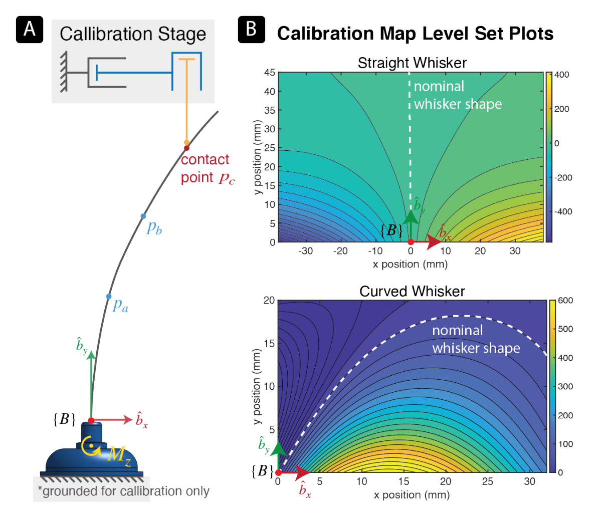
💡 Fig. 1: $P_{a}$ , $P_{b}$ , $P_{c}$ , as contact point along the whisker can cause an exact same deflection moments on it.
Like what it happen to monocular slam, certain mapping from 2D features to 3D point can’t be determined by a single view thus the scalar is unconfirmed, as for a certain deflection moment there‘s infinite possible contact points along the whisker (as it showed in fig. 1). Most of the previous studies focus on building a unique mapping from sensor measurements to contact position. They mostly need a very complex model and stable accurate initialization (which can be quite unrealistic in real use). To avoid that, a unique mapping is unnecessary in this paper, on the other hand introduce proprioceptive motion data in the sequential estimation model as constraint to compensate with that problem. A inverse mapping from contact position to bending moment can be confirmed based on a 5th-order bivariate polynomial model.
To recap it, we don’t have to calculate certain contact from measurements, we only need to know what deflection measurement it would cause by current contact, to build an observation model for state estimation.
We’ll focus on the contact localization algorithm of the paper here in this log, the sensor design and fabrication will be discussed later.
Method
Summarizing the assumptions to limit the scope of the problem:
- The object remain static, thereby the contact point do not changes. It is possible if the contact happens on a tip of rigid rod, like in the figure above, or the corners of an cubic, yet impossible for a convex object. The contact point will shift as sweeping. This change is intentionally ignore since a very fast sampling rate (250Hz) and later compensate by introducing Fading Memory (FM) filter.
- At most one contact point each time, which will be true for convex object.
- Frictional forces along whisker are negligible considering the nitinol material.
- Lateral slip won’t be considered, robot motion and whisker deflection are in a 2D plane.
State Estimation Model
Let {$B$} be the the reference frame of the sensor base and {$S$} be the world-fixed reference frame:
\[x_{k+1}=\mathbf{A}x_{k}+\mathbf{B}\begin{bmatrix}v_{sb}^{b}\\w_{sb}^{b}\end{bmatrix}+w_{k} \\ y_{k}=g(x_{k})+v_{k}\]Where $x_{k}=p_{c}$ is the position vector of the contact point relative to the origin of {$B$} at time-step $k$. $y_{k}$ represents the sensor measurements, thus the function $g(\cdot )$, the sensor model, can be regarded as a mapping from multiple contact position to single deflection moment, which will be discussed at next section. $v_{sb}^{b}$ and $w_{sb}^{b}$ are the linear and angular velocity, respectively, of sensor base {$B$} relative to world-fixed frame {$S$} which is pre-known. Process and sensor noise are modeled where $w_{k}, v_{k} \sim \mathcal{N}(0, \sigma^{2})$.
Given a point $b_{p}$ that is instantaneously coincident to $p_{c}$ but fixed in {$B$}, we can formulate the velocity of contact point $p_{c}$ relative to world-fixed frame:
\[v_{sp_{c}}^b=v_{sb_{p}}^b+v_{bp_{c}}^b =v_{sb}^b +w_{sb}^b\times b_{p} +v_{bp_{c}}^b\]As the assumption.1, contact point remain static in the spatial frame (i.e. $v_{sp_{c}}^b=0$), then the contact point velocity relative to {$B$} is:
\[v_{bp_{c}}^b=-v_{sb}^b+-w_{sb}^b\times b_{p}=-\begin{bmatrix}\mathbf{I}&[\mathbf{p_{c}}]\end{bmatrix}\begin{bmatrix}v_{sb}^b\\w_{sb}^b\end{bmatrix}\]As the sensor is attached to the robot link, $v_{sb}^b$ and $w_{sb}^b$ can be found through:
\[\begin{bmatrix}v_{sb}^b\\w_{sb}^b\end{bmatrix}=\mathbf{J_{sb}^b}(\mathbf{q})\mathbf{\overset{\cdot }{q} }\]To define the process model based on which:
\[x_{k+1}=x_{k}+\delta_{t}v_{sp_{c}}^b=x_{k}-\delta_{t}\begin{bmatrix}\mathbf{I}&[\mathbf{p_{c}}]\end{bmatrix}\xi_{sb}^b+w_{k}\]which gives as $\mathbf{A}=I$ and $\mathbf{B}=-\delta_{t}\begin{bmatrix}\mathbf{I}&[\mathbf{p_{c}}]\end{bmatrix}$.
Sensor Model and calibration
To build mapping (sensor model, $g(\cdot)$) from multiple contact position to one certain deflection measurements on whisker base:
- To gather data for this mapping it used a calibration stage composed of two orthogonal prismatic joints and a thin rod attached vertically at the tip of the end-effector (illustrated schematically in fig.1). It exactly submits to the assumption. 1 that the contact position should be static along the robot motion. The end-effector stage is driven to deflect the whisker with the dowel pin, position and magnetic sensor data are recorded.
- A 5th-order bivariate polynomial model was used to fit the calibration data.
Others
Static assumption can hardly maintain true for the contact travel along the contour of large radius curvature objects, if so, the velocity of contact point relative to world-fixed frame $v_{sp_{c}}^b$ is non-zero. The state estimation model choose to temporarily ignore that non-static error since the sampling rate is quite fast as 250Hz, contact point can not move far between the iterations. Later to compensate that errors, it introduces a Fading Memory (FM) filter (which scales the prior covariance by a factor $\alpha=1.004$ at every time-step) in the model.
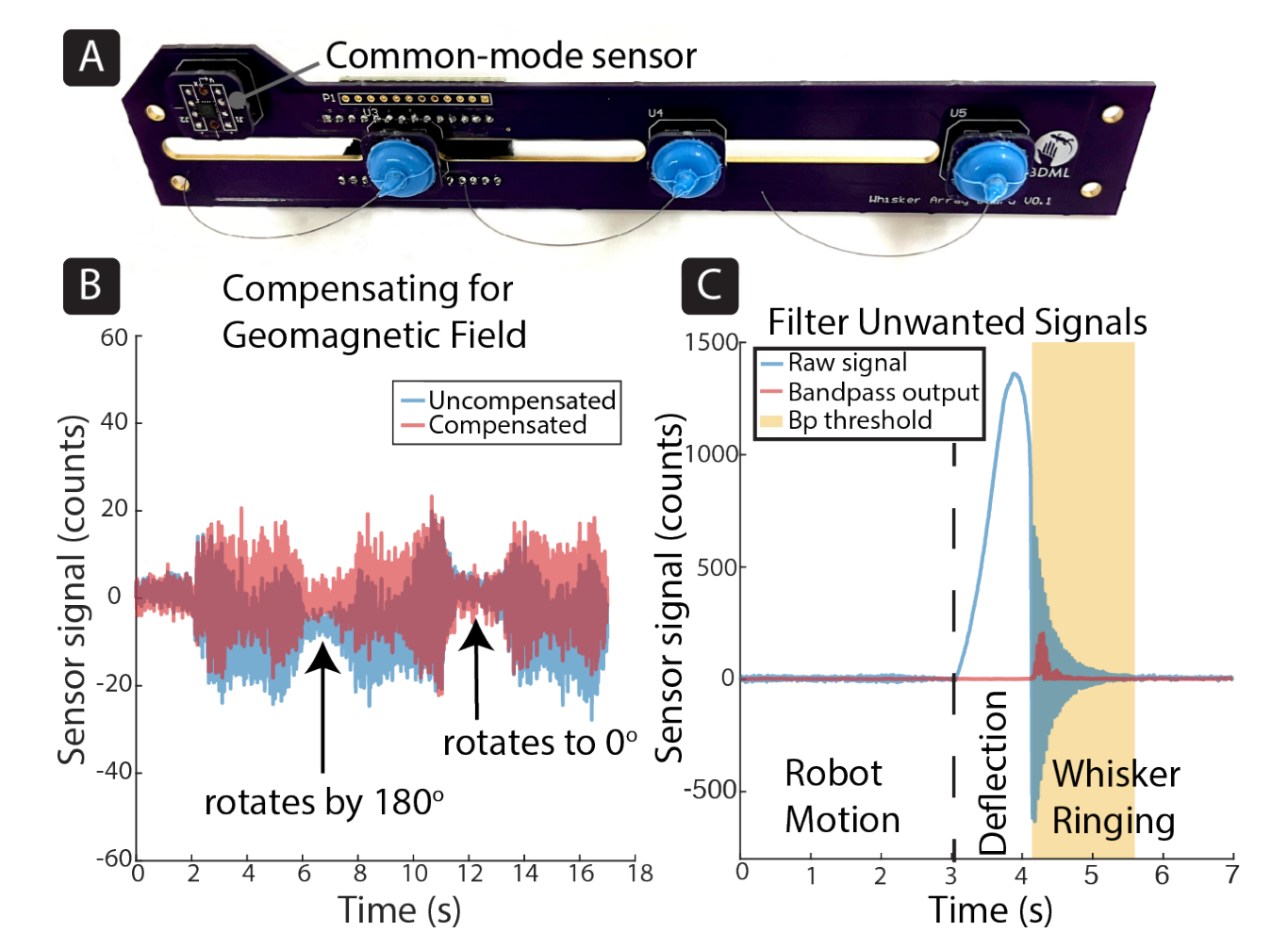
Meanwhile, two general issues were also put into consideration: induced vibration from robot actuators & ringing oscillation when breaking contact from object. Vibrations from robot motion can be mostly ignored as they account for less than 3%of the maximum sensor signal. To compensate the oscillation, it applied a 6th order Butterworth band-pass IIR filter and used a threshold of filtered output to detect these lost-contact events. By the way, it also designed each array with a common-mode reference to compensate for the geomagnetic filed.
Discussion
This work significantly differentiates itself from other previous work based on formulating the contact localization as a sustained state estimation problem. A unique mapping from sensor measurements to contact position is not necessary, on the contrary, an inverse mapping was built for an observation model.
To be specific (vs baseline):
- probabilistic rather than estimation that are deterministic (i.e. a distribution rather than single values)
- Sensor model was calibrated, while a small deflection Euler-Bernoulli beam model was built
A calculation method, that is to say mapping from sensor measurements to contact position, was built in this baseline work. The methods somehow is also depend on a given last estimation and new measured moment, to build a sustained estimation and give directly deterministic results. We’ll discuss it at Paper Reading: Extracting Object Contours with the Sweep of a Robotic Whisker Using Torque Information.
By the way, there’s another advantage of this algorithm. The proposed calibration method is much more generic to different types of whisker, since a complex model was avoided.
Experiments
Experiments Result Visualization
- Each experiment consisted of 10 trials of data collected at 250Hz using the 2-Dof calibration stage. In each trial, the whisker makes contact and stays in contact with the thin dowel pin as it traces an arbitrary trajectory.
- Objects of different shapes were moved into contact, to test the Bayesian filters on moving contact. The straight whisker moved laterally back and forth three times.
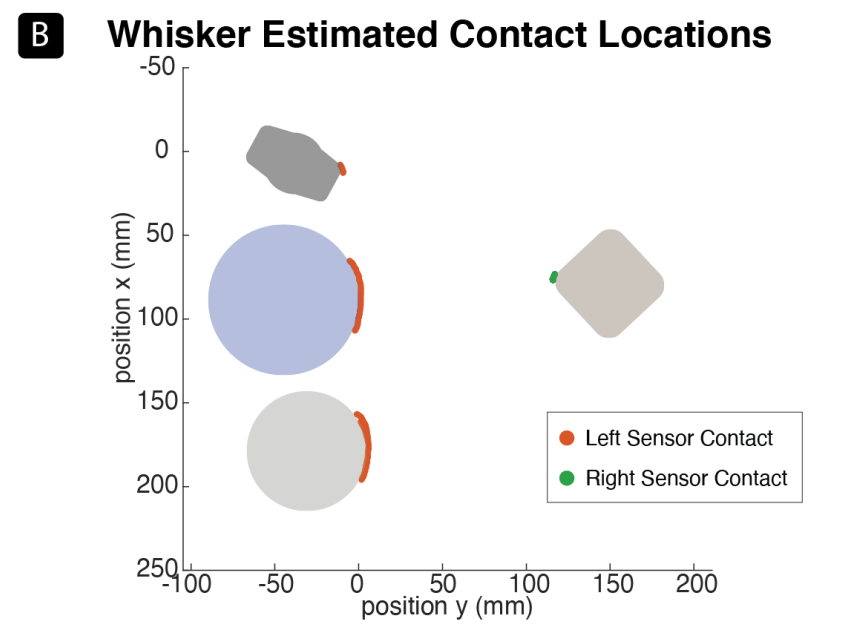
In the system demonstration, two curved whisker arrays that are attached to both sides of the end-effector, where each sensor is individually calibrated. The arm is commanded to move the end-effector in a pre-planned trajectory such that the whiskers on both sides brush against the objects’ surfaces.
 System Demonstration Results Visualization
Update: 14-11-2023
- Storyline: It is the whole point to passively percept a bunch of freestanding objects which were amidst clutter in an unconstructed environment and without disturbing on their state. That’s why mechanical contact as another modality sensor data was introduced, a pre-curved shape whisker was create, a passive approach which subject to robot motion was introduced , and it’s necessary to deal with the motion vibration and ringing oscillation.
Transduction Principle:
Contacts along the whisker produce rotations at the base, which change the magnetic flux measured by the Hall effect sensor. The transduction principle is similar to that in [26] but with substantially lower stiffness ($0.17 mNm/rad$ vs. $3.2mNm/rad$) and designed for incorporation into an array
It is still not clear how the author obtain this moment measurement from magnetic readings. Is a custom analytical model according to the special-designed mechanical structure or just another characterized calibrated model for moments calculation?
Both of them seems not promising, since
- the mechanical structure is totally different from that in [26], and it will be a whole new story if the author want to build its own analytic model. The whisker sensor design in this article include different whisker shape and a silicone-made suspension dome and coupling device;
- the nominal stiffness for whisker sensor is $0.17 mNm/rad$ and there’s currently no F/T sensor could support such a sensitive moment detection. For example, the general minimum signal noise of MiniONE Pro, Bota, is $0.1 mNm$ under a 100Hz sampling rate, and it supposed to be the most sensitive sensor of all Bota series products.
… we integrate instantaneous bending rotations at the whisker base due to whisker deflection, as well as motion of the whisker base over time. Base bending rotations are proportional to the whisker bending moment.
I have no idea what that “proportional” means here, and what that “base bending rotations” represents of. Or the actual moment measurement is not actually important here, we just want a quick easy representation of whisker deflection state, instead of 3-dof magnetic vector???
Another distinction between our method and this baseline is that our sensor model is calibrated, while the baseline uses a small deflection Euler-Bernoulli beam model. In our implementation of this baseline, we used our calibrated sensor model to obtain predicted moments ($M_{i+1}$) and the arc-length to torque ratio ($\frac{ds}{M_{i}}$) which are used for the estimation correction step.
The baseline model adopted a rotation actuator to measure the moment, it supposed to be more trustworthy comparing with a transduction procedure from magnetic readings, and so as to say the calibrated sensor model here for moment prediction. So I found it’s reasonable if the baseline method which count on an accurate moment measurement and mechanical analytic is not promising enough here. I’m not sure…

