Extracting Object Contours with the Sweep of a Robotic Whisker Using Torque
Original Paper: Extracting Object Contours with the Sweep of a Robotic Whisker Using Torque Information
We have discussed how to built a state estimation model for contact localization algorithm in Paper Reading: Whisker-Inspired Tactile Sensing for Contact Localization on Robot Manipulators, that an inverse mapping function $g(\cdot)$ from contact position to sensor measurements is built for observation model. Well, now we have a very clear objective in this log, to understand how the previous mentioned unique mapping from sensor measurements to contact position was achieved.
By the way, it introduced a torque sensor base in this work, not a hall effect sensor, and the whisker mostly is purely rotated against the object, linear translation sweep with a quite different calculation model. But never mind, it doesn’t matter on our discussion temporarily.
Before the discussion on technical approach, it is important to understand three distinct ways that a whisker can slip along an object: lateral slip & longitudinal slip & axial slip.
Lateral slip: the angle of friction cone is not large enough to prevent out-of-plane movement, expand to a 3D spatial scene.Longitudinal slip: contact point change along object surface and whisker length, caused by convention motion of end-effector in 2D-plane.Axial slip: contact point move solely along the whisker length, for example, if a whisker rotates in a plane against a point object, the location of contact on the whisker will change but the location of object contact will remain constant.
Method
Two general hypothesis were made:
- Bends only within its plane of rotation, no lateral slip, that is to say, a 2D scene
- Contact occur at a discrete point along the whisker length no at the tip
Determining the Initial Contact Point
What happened before initial contact and right after it for just few seconds?
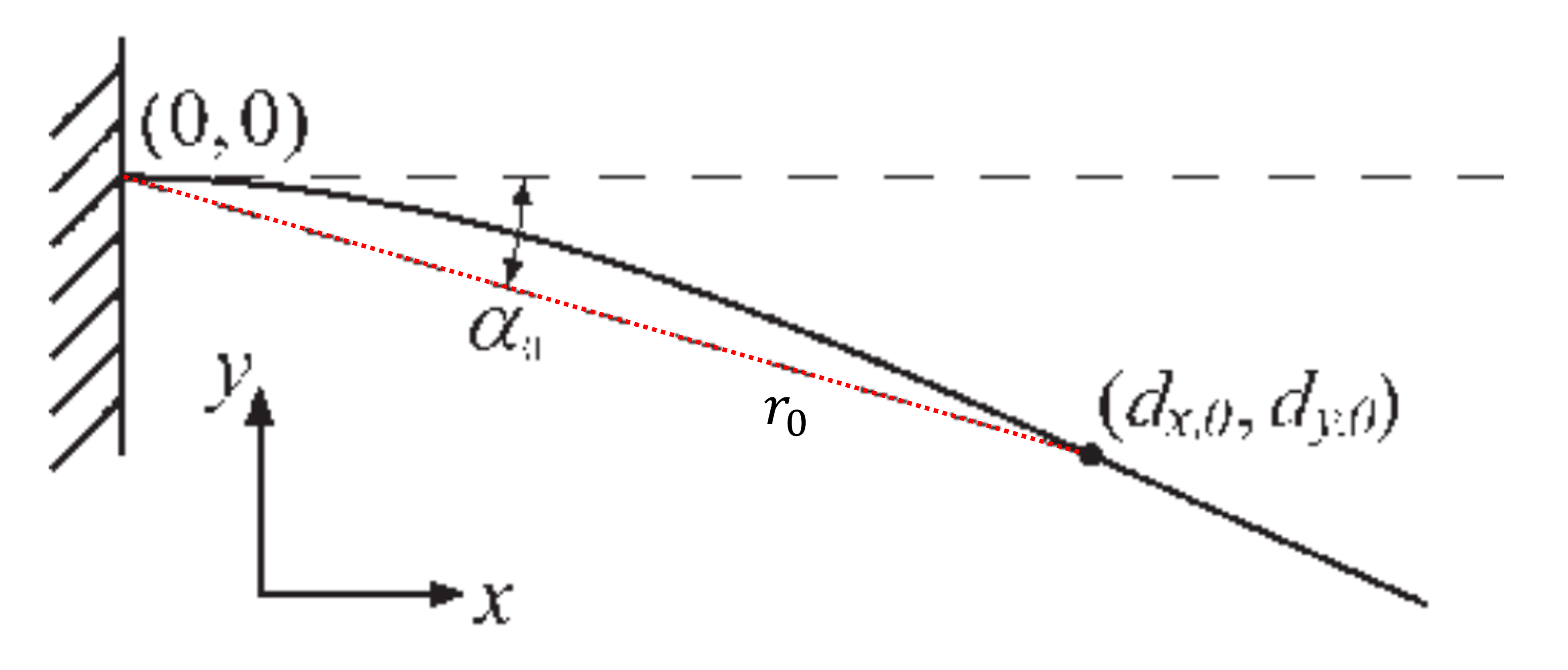
Motion vibration and actual initial contact can be hard to distinguish, therefore a moment threshold $M_{thresh}$ is set, when that is exceeded, indicating initial object contact happen. Two angle records matter here: $\psi_{contact}$, current absolute whisker base angle relative to world-fixed frame, used later to transform the contact position; $\alpha_{0}$, a small push angle beyond initial contact (where $M_{thresh}$ is reached), the contact has actually last for seconds before this moment, but considering we have to distinguish it from a convention motion vibration, we have to tolerate this delay.
💡 Fig.1 The magnitude of $\alpha_{0}$ is exaggerated here, as $3^{\circ}$ is typically sufficient.
OK, now, we have to determine this very first contact position (actual contact has already happened seconds before) in base body frame, and set a good beginning for the following estimation.
\[\begin{bmatrix}d_{x,0}\\d_{y,0}\end{bmatrix}=\begin{bmatrix}r_{0}\\-r_{0}\cdot \alpha _{0}\end{bmatrix}\]$r_{0}$ represents the estimated radial distance of the first contact point, and it can be calculated:
\[r_{0}=3\mathit{EI}\frac{\alpha_{0}}{\mathit{M}_{0}}\]where $\mathit{E}$ is the Young’s modulus, $\mathit{I}$ is the area moment of the inertia and $M_{0}$ is the moment sensed in the plane of rotation at the whisker base. It also assumes that $\alpha_{0}$ is small, so that $\sin \alpha_{0} \approx \alpha_{0}$.
As the whisker continues to rotate against the object, the contact point will slip along the object in a way that depends on the local shape of the object. After this initialization, it follows the sweeping algorithm to infer that local shape based on continued measurement of torque.
Determining Additional Contact Points
The basic premise of the algorithm is that given the current (iteration $i$, $i\ge0$) estimated contact point location relative to the base $(b_{x,i}, b_{y,i})$ (or $(r_{i}, \theta_{i})$ in polar coordinates), its new position after a small incremental rotation $d\alpha$ can be inferred based on the new measured moment $M_{i+1}$.
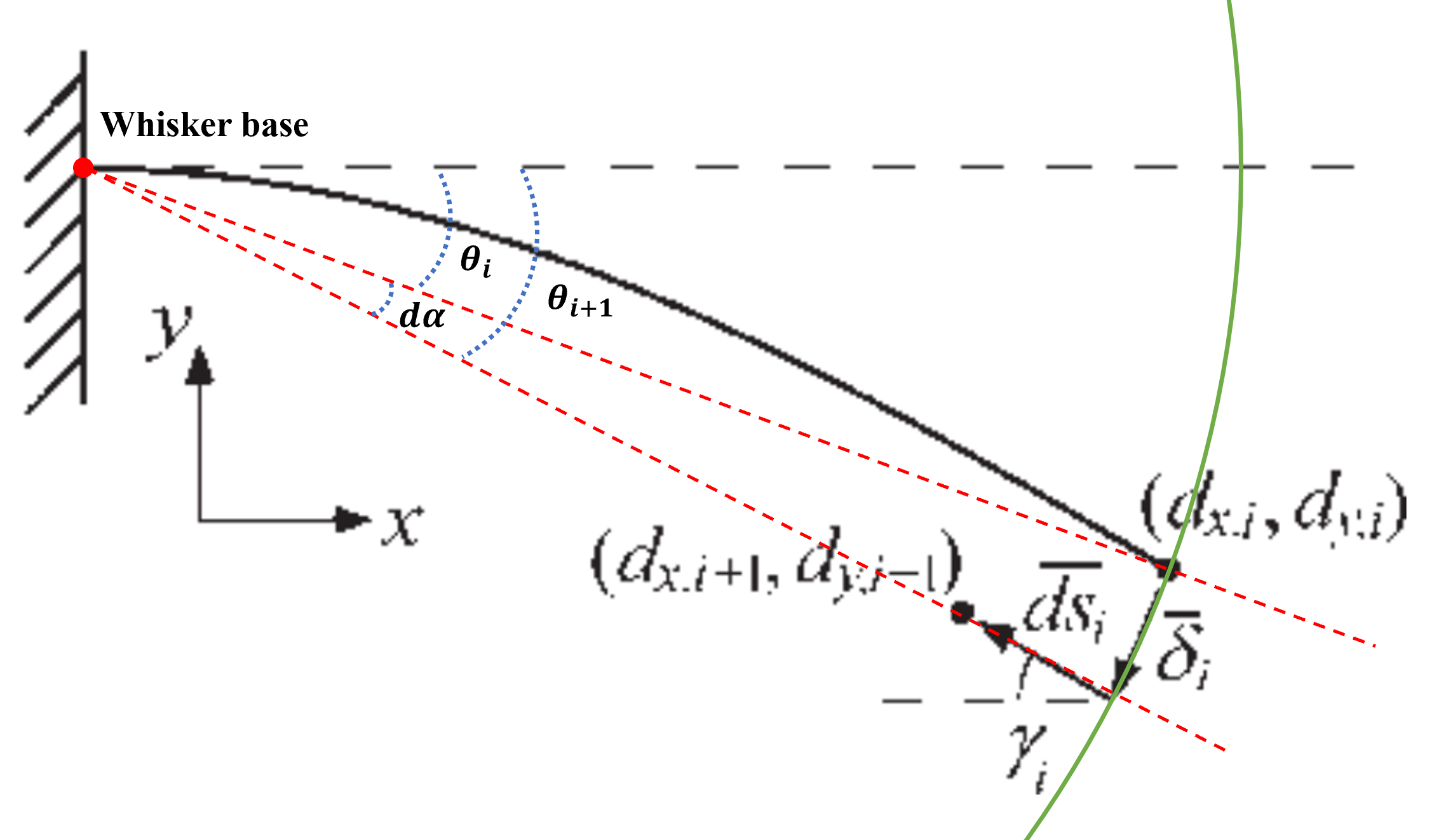
To build sequential estimation along rotated sweeping, the derivation begins by decomposing the translation of the contact point during a single into two non-orthogonal components.
 Fig.2 Non-orthogonal components of the derivation
One of the components is a nominal deflection $\overline{\delta_{i}}$ tangent to the imaginary circle centered at the base and intersecting the current contact point $(d_{x,i}, d_{y,i})$. The second component $\overline{ds_{i}}$ represents the longitudinal slip, occurring parallel to the longitude axis at the contact point (contact angle $\gamma_{i}$) and pointing towards the base. The longitude axis can be regard as the project line from base to contact point, as far axial axis, it should along the length of whisker even curved.
\[\begin{bmatrix}d_{x,i+1}\\d_{y,i+1}\end{bmatrix}=\begin{bmatrix}d_{x,i}\\d_{y,i}\end{bmatrix}+\overline{\delta_{i}}+\overline{ds_{i}}\]So finally the objective became calculate two elements: $\overline{\delta_{i}}$ and $\overline{ds_{i}}$.
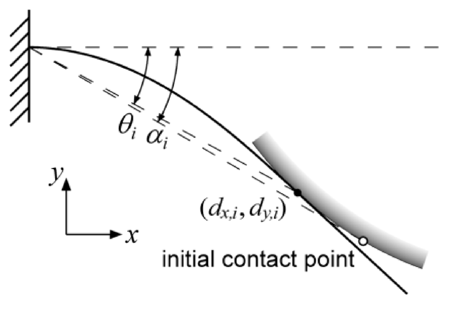
By the way, author put a lot of description here trying to differentiate $\alpha$ from $\theta$. The deflection angle $\theta$ is defined as the angle between the line tangent to the whisker base and the line that connects the whisker base to the current contact point that is:
\[\theta_{i}=\tan^{-1} (\frac{-d_{y,i}}{d_{x,i}} )\]where the negative sign ensures that $\theta$ is a positive quantity. The rotational angle $\alpha$ is the total angle that the whisker has rotated since object contact.
In the absence of longitudinal slip (e.g. a point-object or the sharp corner of an object), they are identical. It is also negligible during the initial rotation, i.e. $\theta_{0}\approx\alpha_{0}$. I put it out separately, because I still haven’t figured it out how it is matter of this total angle $\alpha$ for this work.
Nominal deflection $\overline{\delta_{i}}$
According to the Fig.2, the result of the $\overline{\delta_{i}}$ component is immediately evident, shifting the contact point by magnitude $r_{i}\cdot \alpha$ concentric with the base:
\[\overline{\delta_{i}}=-r_{i}\cdot d\alpha\cdot \begin{bmatrix}\sin \theta_{i}\\\cos \theta_{i}\end{bmatrix}\]Longitudinal slip $\overline{ds_{i}}$
Finding the direction (angle $\gamma_{i}$)
It is straightforward to us Euler-Bernoulli beam theory applied to the classical model of a cantilever beam with concentrated end load, that
\[\gamma\approx\frac{3}{2}\theta\]However, assumptions of linearity are violated for angles larger than about $10^{\circ}$, and hence it turns to a numerical elastic model to compute the relation between $\gamma$ and $\theta$ for larger deflection.
Fig.3 Contact angle and deflection angle for a cantilever beam with concentrated end load & Error incurred using as function of $\theta$
Using the results of the numerical model, Fig.3 plots $\gamma$ versus $\theta$ for up to $\theta=60^{\circ}$. The former equation surprisingly continues to hold with very high accuracy well past the regime where small angle assumptions are valid. Since sweep of less than $60^{\circ}$ are likely to be used in practice, it is a very good approximation and thus is used to estimate the orientation of $\overline{ds_{i}}$.
Calculating the magnitude $\mid ds_{i} \mid$
The magnitude of $\overline{ds_{i}}$, which (neglecting friction) depends entirely on the curvature of the object at current contact point. If the curvature is infinite then $\mid ds_{i} \mid =0$; otherwise, $\mid ds_{i} \mid >0$. To estimate $\mid ds_{i} \mid$ when it is non-zero, it express that as a function of the new moment at the whisker base $M_{i+1}$ as well as other two numerically computed quantities:
\[M_{i+1}=M_{\delta,i}+\frac{dM_{i}}{ds}\cdot \left | ds_{i} \right |\]Defining $M_{\delta,i}$ as the moment after deflection $\delta_{i}$ and $\frac{dM_{i}}{ds}$ as the rate of change of moment with respect to $\mid ds_{i} \mid$ (following along the beam towards the base). Solving for $\mid ds_{i} \mid$,
\[\left| ds_{i} \right|=(M_{i+1}-M_{\delta,i})\cdot\frac{ds}{dM_{i}}\]Consolidating,
\[\overline{ds_{i}}=(M_{i+1}-M_{\delta,i})\cdot\frac{ds}{dM_{i}}\cdot\begin{bmatrix}-\cos (\frac{3}{2}\theta_{i})\\\sin (\frac{3}{2}\theta_{i})\end{bmatrix}\]
Final derivation
Finally, combining all the components to derivation,
\[\begin{bmatrix}d_{x,i+1}\\d_{y,i+1}\end{bmatrix}=\begin{bmatrix}d_{x,i}\\d_{y,i}\end{bmatrix}-r_{i}\cdot d\alpha\cdot \begin{bmatrix}\sin \theta_{i}\\\cos \theta_{i}\end{bmatrix}+(M_{i+1}-M_{\delta,i})\cdot\frac{ds}{dM_{i}}\cdot\begin{bmatrix}-\cos (\frac{3}{2}\theta_{i})\\\sin (\frac{3}{2}\theta_{i})\end{bmatrix}\]OK, leave us with two new unknown variables $M_{\delta,i}$ and $\frac{dM_{i}}{ds}$……
Again, the numerical model is used to approximate, as showing below:
The curves are normalized using $r$ as a scaling parameter, so that $M_{\delta}$ has the units of $[EI/r]$, and $\frac{dM_{i}}{ds}$ has units of $[EI/r^{2}]$. It also shows the results of cubic polynomial fits to both curves (dashed lines), which serve as methods of implementing these relations. The polynomial contain no degree-zero term since the underlying function passes through the origin, and were fit by minimizing the sum of squared errors.
At last, all the needed elements are settled. The current contact point respect to the current local reference frame is finally calculated at each time step. And the transformation to world-fixed frame is still needed:
\[\begin{bmatrix}d_{X,i}\\d_{Y,i}\end{bmatrix}=\begin{bmatrix} \cos \psi_{i} & \sin \psi_{i}\\ -\sin \psi_{i} & \cos \psi_{i}\end{bmatrix}\begin{bmatrix}d_{x,i}\\d_{y,i}\end{bmatrix}\]where $\psi_{i}=\psi_{contact}+\alpha_{i}$.
Discussion
As you can see, the mapping method is extremely complex, nevertheless there’s still a lot of unfolded details, like the Euler-Bernoulli beam theory. This calculation also lacks of generic ability on different types of whisker design with varied shapes and material. All the approximations have to be rebuilt based on the new whisker sensor.
The other follow-up works of this author will be discussed later, where further development on unique mapping from measurements to contact location will be demonstrated.

