Determining the Three-Dimensional Location of Object Contact Based on
Original Paper: Tactile Sensing with Whiskers of Various Shapes: Determining the Three-Dimensional Location of Object Contact Based on Mechanical Signals at the Whisker Base, and Whisking Kinematics Enables Object Localization in Head-Centered Coordinates Based on Tactile Information from a Single Vibrissa
We here only examine the bending moment, which consists of its magnitude and direction, along with the uniqueness mapping to contact location based on it. There were so many other details in these two papers are temporarily passed.
Objective
Basically, in this log, it means to answer how the magnitude and direction of bending moment $(M_{B}, M_{D})$ became the most important component of mechanical signals for contact localization.
- General Proposal
It has been previously revealed that the contact localization can be uniquely determined given six axis of load cell (that is to say full 6 components of forces and torques at whisker base). It is bulky and expensive. To avoid it, the paper aimed to find a triplet that only three of the six mechanical variables at the whisker base could be used, creating unique mapping to the 3D contact point location. Meanwhile, four different profiles of whisker shape were introduced in the experiment: cylindrical straight, cylindrical pre-curved, tapered straight, tapered pre-curved.
Overview
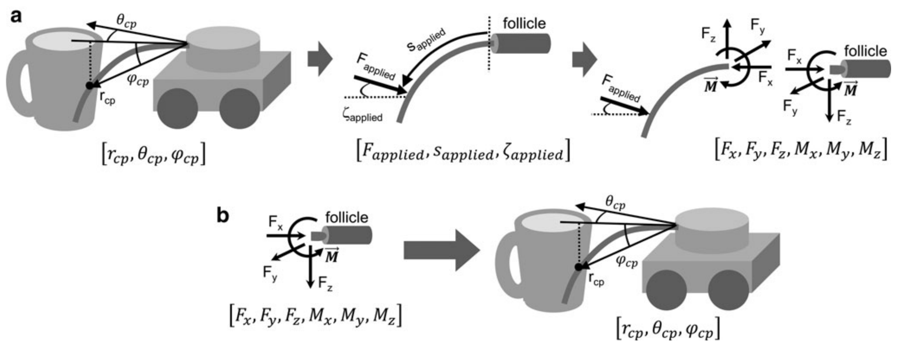
 Fig 1. Graphical depictions of a 3D contact point location resulting in mechanical signals at the whisker base and a mapping of the inverse.
The contact point was described in a nonstandard spherical coordinates $(r_{cp}, \theta_{cp}, \varphi_{cp})$. The contact exerts an external point force on the whisker which is described by $(F_{applied}, s_{applied}, \varsigma_{applied})$. $F_{applied}$ is the magnitude of the applied force, $s_{applied}$ is the arc length from the whisker base to the location of external force, and the $\varsigma_{applied}$ represents the orientation of the force about the axis of the whisker. The applied force creates reaction forces and moments at the whisker base. The components are generally expressed in Cartesian coordinates, $[F_{x}, F_{y}, F_{z}, M_{x}, M_{y}, M_{z}]$ (which are the typical readings from 6-axis force/torque sensor), here transform it into cylindrical coordinates $[F_{x}, F_{T}, F_{D}, M_{x}, M_{B}, M_{D}]$ given the radial symmetry of whisker base.
Whisker-centered coordinate
$F_{x}$ is the axial force directed along the axis of the whisker at its base. $F_{T}$ is the magnitude of the transverse force defined by $F_{T}=\sqrt{F_{y}^{2}+F_{z}^{2}}$; $F_{D}$ is the direction of this transverse force defined as $F_{D}=atan(\frac{F_z}{F_y})$. $M_x$ is the twisting moment about the whisker’s axis at the base; $M_B$ is the magnitude of the bending moment, defined by $M_B=\sqrt{M_y^2+M_z^2}$ and $M_D$ is the direction of the bending moment defined as $M_D=atan(\frac{M_z}{M_y})$. All these forces and moments are described in whisker-centered coordinates (X axis is along the whisker length).
The whole purpose was to characterize and construct mappings from forces and moments at the whisker base to the 3D contact point location. To build this “inverse model”, the first step is to generate mechanical sensor data from pre-known contact point through a simulation model, Elastica 3D (quasistatic and frictionless). Then to validate its uniqueness.
- Generate F/T data: “Contact Point Model”
- Determine the uniqueness: Visual inspection and neural network
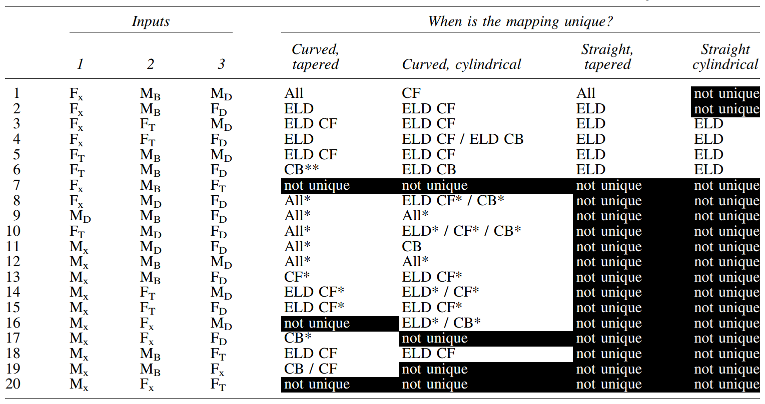
 Table 1. Conditions in which each mapping for each whisker profile is unique
Three mechanical signals at the base of a tapered whisker are sufficient to determine the 3D location of a contact point.
Whisker Array under Rodent-head-centered Frame
Original Paper: Whisking Kinematics Enables Object Localization in Head-Centered Coordinates Based on Tactile Information from a Single Vibrissa
Simulated pegs with fixed position and 1-mm spacing (resolution) apart from others & Tapered pre-curved whisker array with constant scale (length) in same column
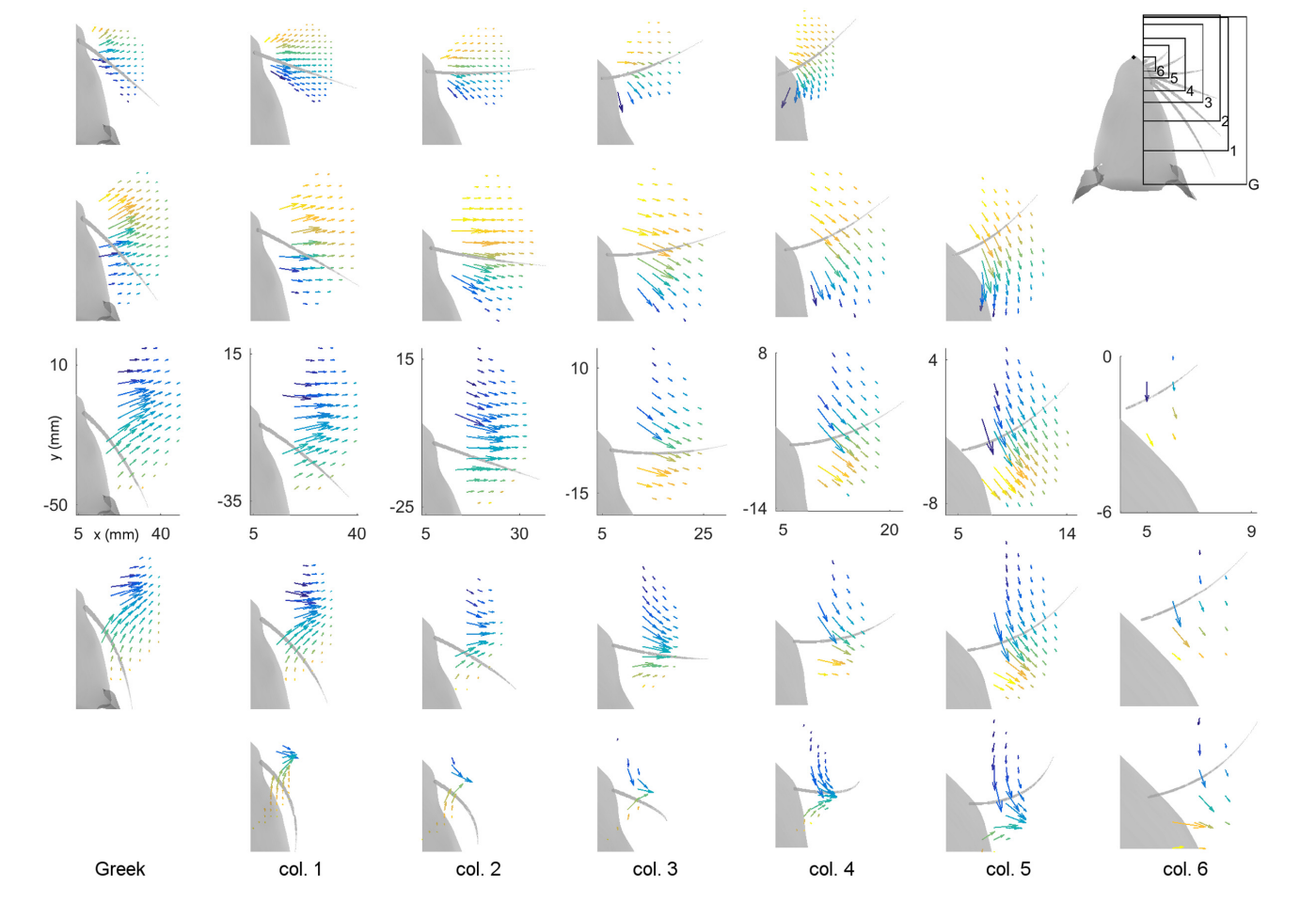
 Fig 2. Magnitude and direction of bending moment at the whisker base after a $5^\circ$ rotation against pegs placed at different $(x, y)$ locations relative to rat’s head.
There’s a perception range and resolution issue here.
- Rostral whiskers were able to reach more anterior pegs; there is more variability between rows than between columns; and in general, whiskers in rows B and C reach the most pegs.
- The direction of bending varies primarily with the peg’s anterior/posterior location, while the magnitude of bending varies more with radial distance.
Although the figure illustrates the direction of bending moment in the $(x, y )$ plane, the direction is actually a combination of the tow bending moment in the y- and z-directions in whisker centered coordinates. It focus on the uniqueness mapping from $(M_{B}, M_{D})\longrightarrow(x, y)$ , 3D scene seems to be temporarily ignored.
 Fig 3. Mappings for the Column-2 whiskers are generally unique, typical of all whiskers of the array.
Of the 31 whiskers tested in the array, 30 reached sufficient number of pegs (range) to generate surface plots that could be analyzed for uniqueness. Of the 30 surface plots, 11 gave completely 100% unique results, ten were more than 98% unique, six were more than 95% unique and the remaining three were more than 92% unique.