A Magnetically Transduced Whisker for Angular Displacement and Moment Sensing
Original Paper: A Magnetically Transduced Whisker for Angular Displacement and Moment Sensing
We may have noticed that in one of my another paper reading log about whisker sensor, a bending moment is frequently mentioned as a mapping target from contact position, even thought they were using a magnetic hall effector. It is wired where they get this moment originally. So this is the paper which can answer the question.
General Proposal
Considering the previous important researches about whisker-inspired tactile sensor, which mainly built upon 6-axis Force/Torque sensor, like Extracting Object Contours with the Sweep of a Robotic Whisker Using Torque Information and Tactile Sensing with Whisker of Various Shape: Determining the Three-dimensional Location of Object Contact Based on Mechanical Signals at the Whisker Base, the moment is proved to be the most important feature for contact localization.
Accordingly, the whole point of this paper is to build an approach to calculate this bending moment and also angular displacement for the whisker from a magnetic sensor (since it only provide a magnetic field change along 3-axis), which is much cheaper, small, easy to construct and with a high resolution and large detect range. The purpose can be demonstrated below:
\[\bigtriangleup \vec{B_{(s)}}(=\left [ \bigtriangleup B_{x}, \bigtriangleup B_{y}, \bigtriangleup B_{z} \right ])\longrightarrow \theta , \varphi , Moment (M_{x}, M_{y})\]Two proposed models:
- A mechanical suspension with four planar serpentine springs was also built for the upper whisker body, so it can deflect and cause the field change on sensor point by a magnet stick on it, when a contact happened along the whisker. Based on that, a combined analytic model was built to complement the experiment. To be specific, it related a magnetic field change on the sensor point to angular deflection of the whisker and then finally to the moments at the base.
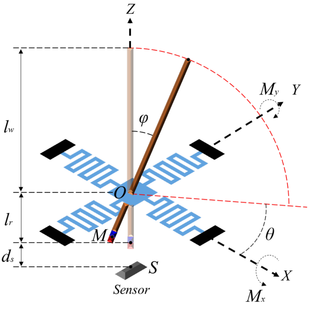
 Fig 1. Mechanical model of the whisker sensing system with modeling parameters
- The analytic model does not provide a perfect prediction in its current form due to fabrication tolerances and magnetic sensor tolerances, therefore, instead of that, a calibrated model was also extracted using a Gaussian Process Regression.
Analytic Model
Basically it contains two part of calculation: a Spring system analysis and a Magnetic field modeling, in order to build relation from magnetic field change to angular deflection then to moments. We won’t dig into the details of calculation, since it is much more obvious if you go directly to original paper. Two important previous researches were cited there respectively in two parts to build the following model.
- Spring system analysis
Fabrication and analysis of awl-shaped serpentine microsprings for large out-of-plane displacement
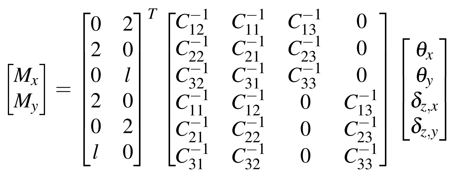
It is first step to understand how whisker rotations translate to forces and moments. Based on the referenced work here, It dissembled the spring into straight beam elements to calculate the mechanical stiffness of the serpentine spring system. The external load can be related to corresponding deflections, the results is as follows:
Ok, $\left \langle \theta, \varphi \to M_{x}, M_{y} \right \rangle$ was built.
- Magnetic field modeling
Cylindrical magnets and ideal solenoids
The second step is to calculate how changes in the magnet position or choice of magnet relate to the measured 3-axis magnetic field. Based on the referenced work here, it can be used to calculate the magnetic field vector at the sensing point if the origin of the magnet, $M$ is known. This complex relationship is represented as a function $f_{B}(\cdot)$ of the sensing point $S$.
\[\mathbf{R}^{T}\left [ B_{x}, B_{y}, B_{z} \right ] ^{T}_{(S)} = \left [ B_{x}, B_{y}, B_{z} \right ]^{T}_{(M)} = f_{B}(\left [ X_{S}, Y_{S}, Z_{S} \right ]_{M}, R, L, M_{S} )\]Since the magnetic field is actually measure at a fixed coordinate frame of the magnetic sensor, a rotation matrix $\mathbf{R}$ is required for the coordinate transformation from magnet to sensor. It is defined as:
💡 Note here it only calculate a rotation from magnet to sensor, but the translation seems to be temporarily ignored.
OK, $\left \langle \overrightarrow{B_{(s)}} \to \theta,\varphi \right \rangle$ was built.
Experiment
Based on the analytic model, several items were tested here:
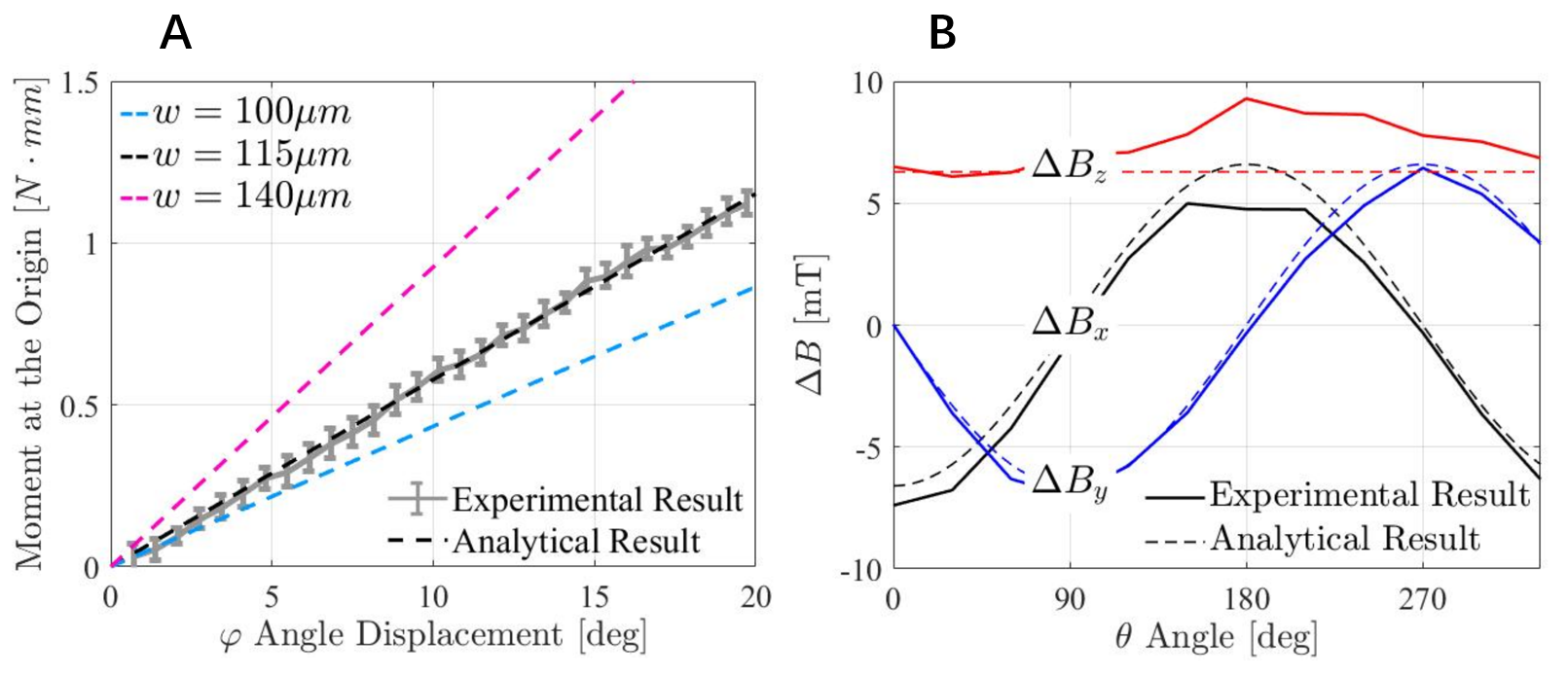
- $[Moment \sim Evaluation\ Angle\ \varphi]$ : with a fixed azimuth angle $\theta=0^{\circ}$, the moment generated at the origin is linearly proportional to the angular displacement. The moment increases linearly up to 1.1N mm when $\varphi$ varies from $0^{\circ}$ to $19.7^{\circ}$. The measured angular stiffness of the spring system for $\theta=0^{\circ}$ is therefore 3.20N mm/rad. In Fig 2A, However the spring width was manually adjust to 115$\mu mm$ fitting the analytical result to experimental result.
- $[Azimuth\ Angle\ \theta \sim Field\ Change\ \vec{B}]$ : with a fixed evaluation angle $\varphi=19.7^{\circ}$, the magnetic field change along three different axis were measured. $\triangle B_{z}$ does not remain perfectly constant as expect in Fig 2B, but with slightly variations likely due to misalignment between the magnet and the sensor.
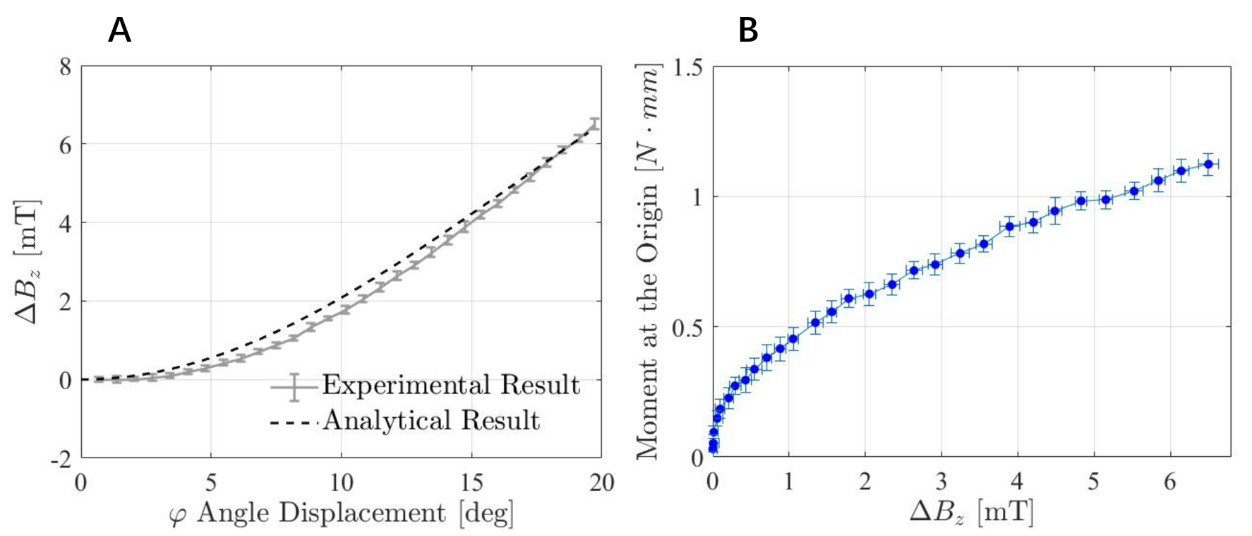
- $[Field\ Change\ \vec{B_{z}} \sim Evaluation\ Angle\ \varphi]$ : with a fixed azimuth angle $\theta = 0^{\circ}$, it shows a clear correlation between $\triangle B_{z}$ and $\varphi$. In Fig 3A, the slopes of the two curves are slightly different which is likely due to variation in the sensitivity of the 3D magnetic sensor.
A clear path from $\bigtriangleup B_{z}$ to $\varphi$ then to moment can be seen from the experiment, if we confined it to a 2D scene with fixed azimuth angle. Like it in Fig 3B, the moment at the origin was linear with angular displacement in $\varphi$, which is correlated to $\bigtriangleup B_{z}$.
Calibrated Model
Clearly, the analytic model can not always produce perfect prediction, considering fabrication tolerance and magnetic sensor tolerances as the items showed in experiment. So characterizing and calibrating each sensor system individually is necessary. Gaussian process regression was extracted from 360 sets of data acquired during experiments: 30 steps on evaluation angle $\varphi$ (0.4 mm/step to a fixed height 33.5 mm), 12 steps on azimuth angle $\theta$ (with $30^{\circ}$ steps), 20 data sets during each step consisted of angular displacement, reaction force and magnetic flux density readings.
The analytic model was just used as a theoretical support for whisker sensor design with different sensitivity and range, it is largely validated by the experiment. But for the real use, a calibration model seems to be more direct and easier.
Update: 13-11-2023
Stiffness - Deflection is restrained on the serpentine spring system
Therefore, moments at the whisker base can be calculated using the known mechanical stiffness of the spring system along with the angular deflection of the whisker. Angular deflection of the whisker can be determined by changes in the magnetic field from the relative position of the magnet and sensor.
In this article, a rigid carbon fiber rod was adopted, which restraints the deflection of sensor system only on the suspension device. In the analytical model, the magnetic field modeling will be used to compute the deflection displacement, azimuth and evaluation angles, from field vector. After that, the mechanical model of spring system was used to calculate the applied moment from angles.
- the system stiffness only depends on serpentine spring system
- otherwise, the angles won’t be able to be measure by motorized stage
- the contact position can be calculated directly from fixed rod length and deflection angle
According to Fig. 2,
\[(19.7^{\circ}\div360^{\circ})\times2\times\pi\times3.20 = 1.1\]The moment increases linearly up to $1.1N mm$ when $\varphi$ varies from $0^{\circ}$ to $19.7^{\circ}$. The measured angular stiffness of the spring system for $\theta=0^{\circ}$ is therefore $3.20 Nmm/rad$
Range & Sensitivity - Detailed evaluation on sensor parameter
The prototype showed a moment sensing range of $1.1 N\cdot mm$ when deflected up to $19.7^{\circ}$. The sensitivity of the sensor was $0.38^{\circ}/LSB$ for the angular displacement sensing and $0.021Nmm/LSB$ for the moment sensing. A fully integrated system is demonstrated to display real-time information from the whisker on a graphical interface.
The only input readings is from magnetic hall sensor, from which it was translated into deflection angles and applied moment. Their measurement range and resolution were therefore tested based on the nominal sensitivity of 3D magnetic sensor ($0.13 mT/LSB$)
deflection angles (mainly focus on $\varphi$) - $19.7^{\circ}$
\[\frac{19.7^{\circ}}{6.8mT}\cdot0.13mT/LSB=0.38^{\circ}/LSB\]to calculate an approximate linear angular sensitivity of the whisker sensor (in $^{\circ}/LSB$) for changes in $\varphi$. The maximum angular displacement of $\varphi$ (range: $19.7^{\circ}$) is divided by the total change in $B_{z}$ ($6.8mT$) and multiplied by the nominal sensitivity of the magnetic sensor.
applied moment - $1.1Nmm$
The moment at the origin was linear with angular displacement in $\varphi$, according to Fig. 3, which is correlated to $\triangle B_{z}$. By plotting the relation between $\triangle B_{z}$ and the moment, the moment sensitivity of the system can be visualized and calculated. At small moments, $\triangle B_{z}$ does not change significantly, but this sensitivity increases at higher moments. Two sensitivities were calculated assuming the same nominal magnetic sensor sensitivity of $0.13 mT/LSB$: full-range and linear-range ($\triangle B_{z} > 1.8mT$) sensitivity.
Full Range Sensitivity:
\[\frac{1.1N\cdot mm}{6.8mT}\cdot0.13mT/LSB=0.021N\cdot mm/LSB\]


